
- Home
- MECHANICAL
- ELECTRICAL
- ELECTRONICS
- SCHOOL PROJECTS
- CIVIL PROJECTS
- ONLINE SERVICES
- DOWNLOAD PROJECTS THESIS/FILE
- CONTACT US
MECHNICAL PROJECTS Online Buy
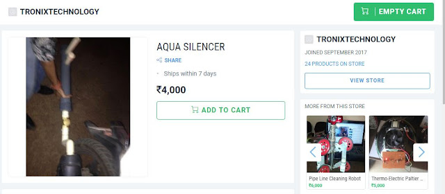
1)(AQUA SILENCER)
An aqua silencer System is designed to replace conventional single unit engine silencers on board structures. With it’s light weight and slender design, it offers a minimal 'footprint' while optimizing the entire exhaust system for low noise and reduced backpressure. It is used to control the noise and emission in IC engines. The reason why we go for aqua silencer is, in today life the air pollution causes physical ill effects to the human beings and also the environment. The main contribution of the air pollution is automobile releasing the gases like carbondioxide and unburt Hydrocarbon. In order to avoid this type of gases by introducing this aqua silencer. It is fitted to the exhaust pipe of the engine, Sound produced under water is less hearable than it produced in atmosphere. This mainly because of small sprockets in water molecules, which lowers its amplitude thus, lowers the sound level. The emission can be controlled by using the activated charcoal layer and it is highly porous and posses extra free valences so it has high absorption capacity. So absorb the gases from the engine and release much less position to the environment. The noise and smoke level is considerable less than the conventional silencer, no need of catalytic converter and easy to install[3]. In this silencer, the Charcoal and Water so it is called hybrid aqua silencer, and it is useful in automobile, industry, DG sets & DG machines, Marin and Boats also so, It is known as hybrid universal aqua silencer.Now a days Air pollution is major problem The main pollutants contribute by automobiles are (CO), UBHC, (Nox) and Lead etc.Other sources such as electric power generating stations, industrial and domestic fuel consumption , refuse burning, industrial processing So it is imperative that serious attempts should be made to conserve earth’s environment from degradation. An aqua silencer is an attempt in this direction, it is mainly dealing with control of emission and noise. An aqua silencer is fitted to the exhaust pipe of engine
Aqua
silencer
·
Basically an aqua silencer consists of a perforated tube which is
installed at the end of the exhaust pipe.
·
The perforated tube -different
diameters. purpose of providing different diameter hole is to break up gas mass
to form smaller gas bubbles.
· Generally 4 sets of holes are drilled on
the perforated tube. The other end of the perforated tube is closed by plug.
·
Around the circumference of the
perforated tube a layer of activated charcoal is provided and further a
metallic mesh covers it.
·
The whole unit is then placed in a water
container.
·
A small opening is at the top of the
container to remove the exhaust gases & a drain plug is provided at the
bottom of the container for periodically cleaning of container.
·
Also a filler plug is
mounted at the top of the container. At the inlet of the exhaust pipe a
non-return valve is provided which prevents the back flow of gases and water as
well.


2)PIPE LINE INSPECTION ROBOT
Abstract The name of our project is pipe the pipe inspecting and cleaning robot (PIAC); in a nutshell it is a robot that will be used to clean the interior of the pipes using a brushing mechanism. One of the critical areas of the oil and gas industry is the transport of oil and other fluids through a network of pipes. Over time these pipes have accumulated amount of slug and other deposits; this leads to decrease in pipeline carrying capacity, reduced reliability, loss of power due to higher pumping pressure required and irregular flow. In the light of the problems mentioned above we have decided to attempt to solve this problem using our PIAC project. This will not only clean the interior of the pipe but also be able to send live video feedback to the personnel on the ground depicting the kind of residues found in the pipes. The robot can also be added with additional sensors to relay any other critical information. During the course of the project we have faced multiple challenges, which were mitigated by the team accordingly using alternatives and prior knowledge through literature review. There are many outcomes of this project. The first being that the set objectives of the project are achieved which in a nutshell was to build a prototype PIAC with the mobility, cleaning and video feedback functionality. The second outcome is that the project has worked effectively to clean the rust that was in a sample pipe. The amount of rust removed for the pipe was about 4 grams cleaning a surface area of 0.398 square meters the fourth outcome of the project is that the team was able to lean many new things about the pipe cleaning industry through the literature review and during building the prototype. The fourth and final outcome of the project is that there is scope of improvement for the project and new engineering standards such as ASME , NEC and IEEE can be incorporated in later builds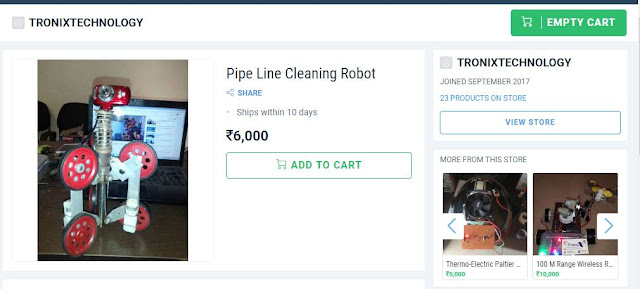
3)THERMO-ELECTRIC COOLING HELMET
ABSTRACT
Human life is so precious and valuable, that it should not be compromised under any cost. The concern over the safety of vehicle drivers has pushed for invention of new equipment that can save lives. According to Statistics from the Insurance Institute for Highway Safety (2010), it is mentioned that nearly 70% of mortality in road accidents occur due to head injury, where the rider has not worn a helmet. It is not that people are very negligent about their lives on road, but that they experience dozens of discomforts by wearing helmets. The most common discomfort is that, heavy sweat occurs due to excessive heat formation. This paper deals with the development of cooling system for biker’s helmet using thermoelectric technology. The system consists mainly of a heat sink, aluminum passageway and Peltier module. The prototype is fabricated and mounted onto biker’s
components used :-
PELTIER
MODULE
HEAT
SINK
AIR
CHANNEL
ELECTRIC
FAN AS AN AIR PUMP
BATRREY
ELECTRIC FAN
COMPLETE DIGITAL TEMPARTURE SENSOR BASED AMPLIFIER CIRCUIT IN HELMET

4)WIRELESS ROBOTIC HAND
IT is an wireless 100m range robotic hand with gripping mechanism controlled by an 4 Chanel RF 433MHZ ,mounted on an robotic four wheel drive,whose control are also controlled by RF.This device can be used for various purposes like checking and placing some bio hazard and explosive material ,this robotic hand can be controlled from 100 m range so that an safe distance will be there in between controller and object.

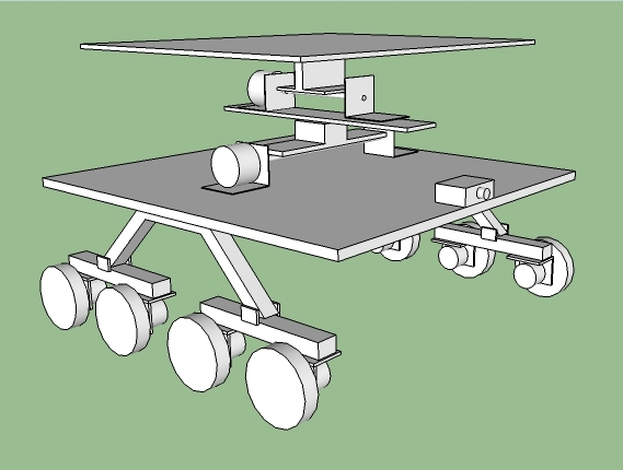
5)MAXIMUM STABILITY VEHICLE FOR LOAD HANDLING
When transporting the heavy loads like bridge parts ,large parts of a thermal power station or any other plants , rockets part, space shuttle where the load more than 1000 tons it becomes necessary to provide a stable platform on which the heavy load is placed & stable surface should be horizontal independent to the road surface.
This stabilization is done with the help of hydraulic jacks which automatically set there position to maintain a stable & horizontal platform.
Our project deals with the design & fabrication of maximum stability vehicle. The vehicle consists of 8 wheels to provide maximum stability through wheels. further stabilization is done by upper platform. It is connected to two dc motors one for each axis & one two axis accelerometer sensor. The sensor senses the tilt of platform with respect to horizontal plane in x & y direction ,now it gives this data to atmega 32 processor which process this data & generate appropriate command to drive two dc motor in such a manner that the platform remain horizontal with respect to the horizontal plane independent to the vehicle tilt on the road .
Vehicle is controlled wirelessly through rf remote control.
So this vehicle provide maximum stable platform through wheels ,flexible platform and accelerometer sensor.
INTRODUCTION
This paper demonstrates the feasibility of designing and building a self-correcting
platform using inexpensive hardware and software . The
platform was designed using inexpensive materials, wood and aluminum sheet metal,
and was controlled by an open source microcontroller, an accelerometer, and two servos.
An microcontroller, hobby grade servos, and a two-degree of freedom (axis)
accelerometer were used to create the controlled platform. The intent of the platform
design is to maintain the platform at an initially selected angle while the support
structure orientation changes. The software was written with logic to convert the digital
data from the accelerometer to an acceleration magnitude vector. The magnitude was
then compared to a predetermined mathematical function to infer the angle of tilt of the
platform. The angle of tilt is then converted to angle of rotation for the servos to act on.
Testing showed the platform to perform as expected. Although some error on the final
angle was expected, the magnitude of the error observed indicated the platform design
has a high sensitivity to low tolerance mechanical joints (slop). Overall the platform
design was validated based on the positional accuracy of the platform given the low
quality components used to create it. In other words, the platform performed greater
than the sum of its parts.


The model is built up of eight wheels all making four pairs of bogie mechanism in which all eight wheels are independent and have their own driving dc- motors to give power drive. The model consist of eight 60 rpm motors to provide the wheels torque and motion and even a further up gradation is done for the platform stability so that it does not tilt and remain horizontal at any condition. The stability of the platform is managed by the use of MMA7361L ±1.5g, ±6g three axes Low-G Accelerometer Module which help to stable the platform at any instance while the robotic vehicle tilts

No comments:
Post a Comment